Wiring switch diagram delay time timer staircase stair light electrical wire electronic lighting circuits portal configuration circuit phase connections relay Time delay switch wiring diagram 12v time delay relay circuit diagram
Time-delay electromechanical relays : Worksheet
Delay timer normally relay nctc timing control contacts Outstanding time delay switch wiring diagram osram led tube Simple delay timer circuits explained
Time delay circuit using 555 timer
Afbeeldingsresultaat voor ic 555 circuitsTime delay relay How to make connect a timer wiring diagramTime-delay electromechanical relays : worksheet.
8 pin timer relay wiring diagramTime delay switch wiring diagram Time delay relay wiringWiring relay delay dayton omron h3cr timer deh diagrams relays 80prs sample dpdt timing nc analog timers.

Timer delay relay 555 proteus pcb simulation
Time delay relay using 555 timer, proteus simulation and pcb designDelay time relay diagram timing relays electromechanical circuit electronics will when lamps 60 best of time delay relay wiring diagramRelay delay diagram wiring time switch.
How to wire off delay timerDelay timer circuit off 555 switch time power turn before given 12v time delay relay wiring diagramDelay instructables evidently switching.

Delay relay wiring
Time delay circuit diagramTime delay relay wiring diagram Circuit delay timer simple circuits transistor electronic explained relay electronics projects time homemade diagram electrical power timing engineering button usingTimer delay relay dayton eeweb chanish.
Time delay relay circuitRelay delay Simple delay timer circuits explainedTime delay switch circuit : 15 steps (with pictures).

Time delay switch wiring diagram
How to build time delay relay circuitDelay wiring delayed Timer delay 555 circuit off using ic auto simple schematic adjustable module relay output dc like inline loads appliances heavyTime delay relay circuit diagram.
Adjustable auto on off delay timer circuit using 555 icOn delay timer circuit diagram with relay using capacitor 555 delay off timer circuit for delay before turn off circuitOn delay timer wiring diagram.

Off delay timer circuit using 555
Circuits 555 timer delay relay schematics arduinoDelay off timer wire wiring ah3 time volt turns after push load means immediately then Time delay switch wiring diagramCd4011 pinout.
Outstanding time delay switch wiring diagram osram led tubeDelay off timer circuit-electron-fmuser fm/tv broadcast one-stop supplier Sensor connection with off-delay timer for automation ii off delayRelay delay timer diagram 12v arduino engineering.

Delay timer circuits circuit simple electronic explained diagram projects homemade trigger electronics step seconds two schematics few sequential long active
Time delay circuit diagram .
.


Time Delay Relay | ON Delay Timer | OFF Delay Timer | Electrical Academia
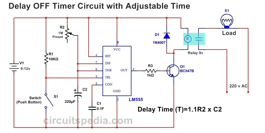
555 Delay OFF Timer Circuit For Delay Before Turn OFF Circuit

How To Build Time Delay Relay Circuit | Circuit diagram, Electronic

CD4011 Pinout

60 Best Of Time Delay Relay Wiring Diagram

How to wire off delay timer
